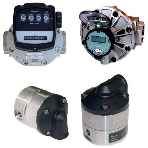
Positive Displacement Flow Meter
 |
FEATURES
|
GENERAL DESCRIPTION
The DOM series positive displacement flowmeter is the preferred choice for measuring viscous liquids such as lubricating/hydraulic oils, diesel fuels, chemicals, solvents, resins, and pastes.
The Oval Gear meters are positive displacement flowmeters where the passage of liquid causes two oval gears to rotate within a precision measuring chamber and with each rotation a fixed volume of liquid passes through the meter. Magnets embedded within the gears initiate a high resolution pulse train output. The pulse output can be wired directly to process control and monitoring equipment or can be used as an input to instruments supplied with or fitted directly onto the meter.
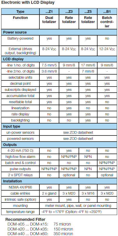
The flowmeter is available as a blind transmitter with pulse output capable of interfacing to most monitoring and control instrumentation or the meter can be fitted with or supplied with instruments such as totalizers, rate totalizers or batch controllers. These instruments also have monitoring and control output options including 4-20 mA, scaled pulse, flowrate alarms and batch control logic (preset metering).
SPECIFICATIONS
| Wetted Material DOM-A05...DOM-A15 Body: Aluminum Gears: Sintered 316 Stainless Steel Bearing: Carbon Ceramic DOM-A20...DOM-A60 Body: Aluminum Gears: Aluminum Bearing: Hardened Steel Rollers (only for lubricating fuels and oil) DOM-S, DOM-H Body: 316L Stainless Steel Gears: Sintered 316 Stainless Steel Bearing: Carbon Ceramic DOM-D Body: Ductile Iron Gears: Aluminum |
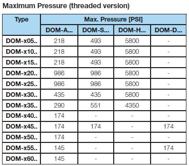
Bearing: Hardened Steel Rollers (only for lubricating fuels and oil) O-Rings: FKM (standard): 5°F to 250°F; EPDM (ethylene propylene rubber): -4°F to +250°F (for ketones only); PTFE encapsulated FKM: -4°F to +250°F; NBR: -4°F to +210°F Cover: Glass Reinforced Nylon Accuracy DOM-x05...DOM-x15: ±1.0% of reading DOM-x20...DOM-x35: ±0.5% of reading DOM-x40...DOM-x60: ±0.2% of reading Repeatability: ±0.03% of reading Protection: NEMA 4X/IP66 Temperature Range Options Z, B, L0: -4°F to +176°F Pulse Output: -4°F to +250°F Electrical Connection: 1/2" NPT |
Pulse Output
Reed switch pulse output
The reed switch output is a two wire normally open SPST voltage free contact ideal for installations without power or for use in hazardous area locations when Intrinsically Safe (I.S.) philosophy is adopted.
Note: When using the reed switch output the liquid temperature must not change at a rate greater than 50 ºF per minute. In general the reed switch life will exceed 2 billion actuations when switching less than 5 VDC/10 mA.
Power supply: max. 30 VDC, max. 200 mA
Hall Effect sensor pulse output
The Hall Effect sensor is a high resolution solid state 3 wire device providing an unsourced, open collector, NPN transistor output. The term “un-sourced” means that no voltage is applied to the output from within the flowmeter, it must be pulled to a “high” or “on” state by between 5 - 24 VDC supplied from an external source, typically the receiving instrument.
The pulse output between signal and -0 V is a voltage square wave with the high level being the DC voltage available at the open collector and the low level being -0 V.
The receiving instrument must incorporate a pull up resistor (typically greater than 10 kΩ in most instruments) which ties the open collector to the available DC voltage level when the Hall sensor is not energized. When energized the open collector output is pulled to ground through the emitter (-0 V).
Power Supply: max. 5-24 VDC, max. 20 mA
Quadrature Hall Effect pulse output (...D0)
Two Hall Effect sensors arranged to give separate outputs out of phase with one another. The quadrature output is typically suited to custody transfer applications where signal integrity verifi cation is required, it is also used for metering bi-directional flow.
Power Supply: max. 8 - 24 VDC, max. 20 mA
Mechanical totalizer (...M4)
The flowmeters type DOM-x20 up to DOM-x60 are available with a mechanical totalizer with a 4-digit resetable totalizer and indication of accumulated total value. The motion of the rotors is transmitted to the mechanical register totaliser via an interfaceing reduction gear train and dynamic seal assembly.
Signal Converter (...L0)
The L0 signal converter option may be set to function as either a frequency to current converter (2-wire 4-20mA output), a pulse divider, or a single point flow rate alarm. The signal board also has an NPN pulse output which mirrors the input pulse frequency, this signal may be used for remote rate and/or total indication.
Power Supply: 24 VDC
Special Cut Rotors for higher viscosities
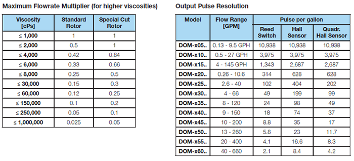
For viscosity > 1000 cP, special cut rotors option "S" should be used to reduce pressure drop. This applies to DOM-x15 and larger sizes. For higher viscosities, the flowmeter max. flowrate is de-rated according to the table above. Example: DOM-x25 measuring oil at 6000 cP, max. flow 40 GPM x 0.5 = 20 GPM new maximum flow rate.
ORDERING INFORMATION
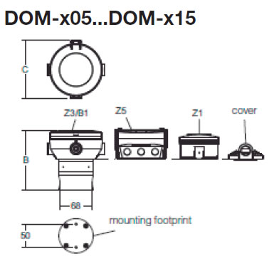
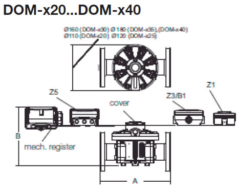
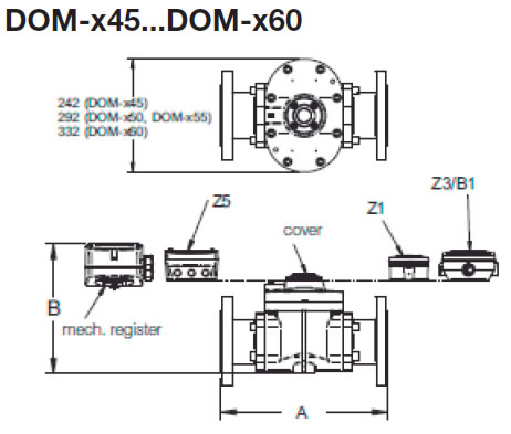
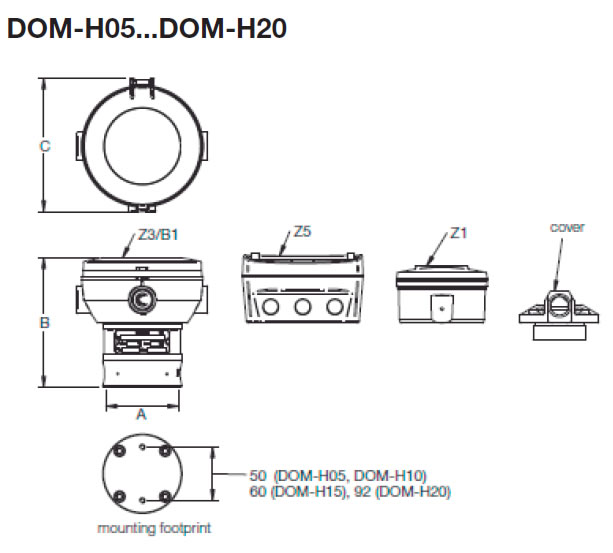
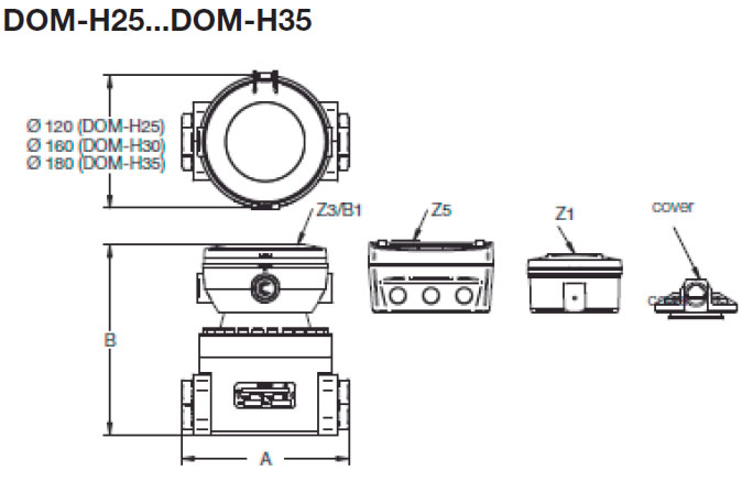
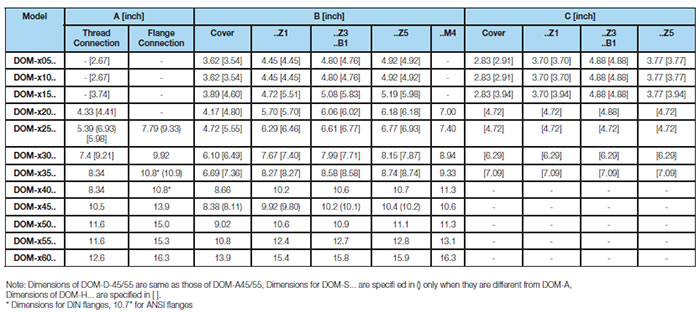
DIMENSIONS
