Articles
WHAT IS THE CALORIMETRIC PRINCIPLE?
The calorimetric principle is a means of monitoring flow rates through thermal energy dispersion.
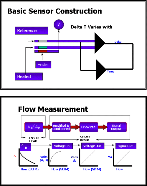
Typically the measurement involves two PTC thermistors embedded in the probe tip or wall of the sensor. One of the PTC thermistors (the reference thermistor) monitors the temperature of the medium being measured (air, water, oil, etc.) while the other is heated a fixed percentage above the reference thermistor. This sets up a differential resistance between the two.
Assume now that the probe tip is sitting in still water in a pipe. The differential resistance is established by the electronics and everything remains stable until flow begins to occur in the pipe. When this happens, the flowing water cools the heated thermistor, thus changing the differential resistance between the two thermistors, proportional to the flow speed. The amount of energy that the electronics uses to attempt to maintain the established differential resistance (by increasing power to the heater of the dynamic thermistor) is used to determine the flow rate. This is then translated into a switching or transmitter output.
“Calorimetric” thus can be described as measuring flow through use of “thermal dispersion” (think of the term “calorie” or unit of heat.)

WHAT TYPE OF MEDIA CAN IT BE USED ON?
Since the calorimetric principle is based upon the thermal conductivity of the medium, it enables measurement of any medium that is thermally conductive. This includes water, oil, acids, grease, and gaseous media such as air, nitrogen, argon, etc.
The sensor is calibrated using a reference of the exact medium or of medium with the same thermal conductivity.
WHY IS THIS METHOD SO GOOD FOR LOW FLOW AND LEAK DETECTION?
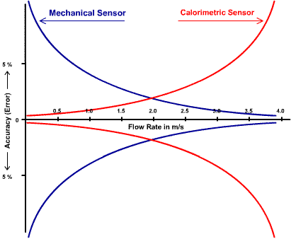
Since the calorimetric principle does not rely on a mechanical means of detecting flow speed as do paddlewheel or turbine sensors, it can sense movement of the media at a fraction of that required by these devices. The instant any flow movement occurs, the sensor reacts. Mechanical devices have inertia to overcome to begin the movement of the mechanical device (the paddlewheel or turbine blade). This is typically in the range of 50 cm/second. Thus flows at or below this level can not be accurately detected. The flow trumpet demonstrates the advantages that calorimetric sensors have at lower flow rates.
Note that at flow rates below 4 meters/second the mechanical sensor’s accuracy dramatically worsens, but then improves as speed increases. Conversely, the “calorimetric” sensor’s accuracy is better as flow rates reduce. It’s greatest accuracy is at the lowest flow rates, where mechanical sensors become the most unreliable.

Vacuum line leak
Air under a vacuum has less thermal conductivity than does air at ambient conditions. The calorimetric sensor, with an adjustable setpoint can be field adjusted to a trip point just above the thermal dispersion point of the vacuum condition. If a leak occurs, the reduction in the vacuum causes an increase in thermal dispersion (similar to an increase in flow rate), cooling the heated thermister and telling the sensor that a leak has occurred, tripping the setpoint.
Compressed air leak
A similar situation (except in reverse) exists with a pressurized line. Under pressure, air condenses, increasing its thermal conductivity. If a calorimetric flow switch is set just below the thermal dispersion point at the desired pressure, a reduction in that pressure will cause the heated thermistor to increase in temperature and provide a switch to alarm that a reduction in pressure has taken place.
Lubrication oil flow leak
If a fixed flow rate for a lubrication process is established under normal operating conditions, a calorimetric flow switch can be used to monitor that the flow rate does not increase due to a broken line, or decrease due to flow failure. Slight increases or decreases in normal flow will be sensed quickly by the calorimetric sensor and be used to provide an alarm or turn off a process.
HOW LOW A FLOW RATE CAN BE MEASURED?
This will depend on the media type and its related thermal conductivity. However, extremely low flow rates can be achieved at very a very reasonable price compared to other technologies.

PRECISION IN MEASUREMENT
One must always be aware of the application and how the installation of a flow sensor can greatly affect the resulting accuracy of the reading. Insertion depth of a flow transmitter into the pipe can have a dramatic effect on the accuracy depending upon the flow profile of the media in the pipe. Where possible, if accuracy is key, an in-line pipe type of flow transmitter or flow switch, which is factory calibrated in a precision flow loop is preferred. The pipe length inherent to the sensor normally will provide the required up – down stream straight pipe requirements and improve the flow profile for the measurement. In addition, calibration data for that specific sensor, from the manufacturer can be used to further linearize the process. Calorimetric sensors are very repeatable (typically <1%) so a fairly precise measurement can be achieved.
